
BESS Configuration
Setting up your BESS profile in Glint Solar
Set up BESS profiles in Glint Solar for a shortcut to quick, reliable, and accurate designs. Create profiles with any and all of the layouts, batteries and MV stations that you use — including details of the specific models, orientation, spacing and losses — and apply them to your designs in click. Profiles let you compare estimated capacity with ease and visualise how your site would look in reality.
At Glint Solar we recommend that you rely on BESS expertise in setting up profiles. Glint Solar includes some example profiles in the product, however, optimal BESS configuration depends on location, specific equipment, company preferences and more. We are very happy to help you set up profiles — especially for users that don't have in-house BESS expertise.
To adjust the BESS (Battery Energy Storage System) configuration, it consists of three main components: the profile, batteries, and MV station. The process begins with defining the batteries, as their capacity and specifications directly influence the system's performance. In the battery selection phase, the following parameters need to be defined. The values provided below are illustrative, and they might differ from project to project and supplier.
BESS configuration available in Glint Solar
You can create and edit BESS configuration in two places in Glint:
1. In the PV configuration window.
Click on the Menu button in the left side panel and select PV & BESS configuration.
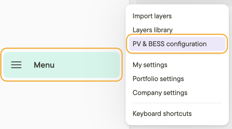
Or click on the speed button to the right of the Profile in use for a new analysis.
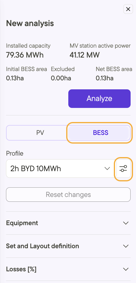
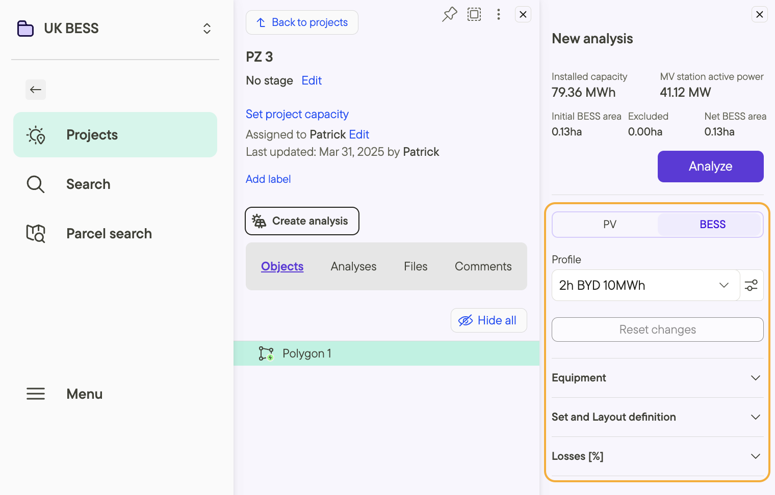
2. When creating a new analysis for a project.
The profile configuration will open in a new modal when you click Create analysis.
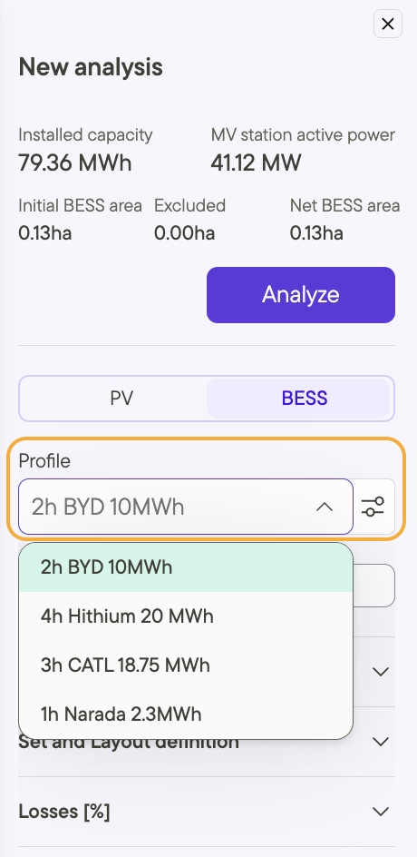
Click on Profile to choose from existing profiles.
You can then make adjustments to the parameters in the Equipement, Set & Layout and Losses sections.
Battery:
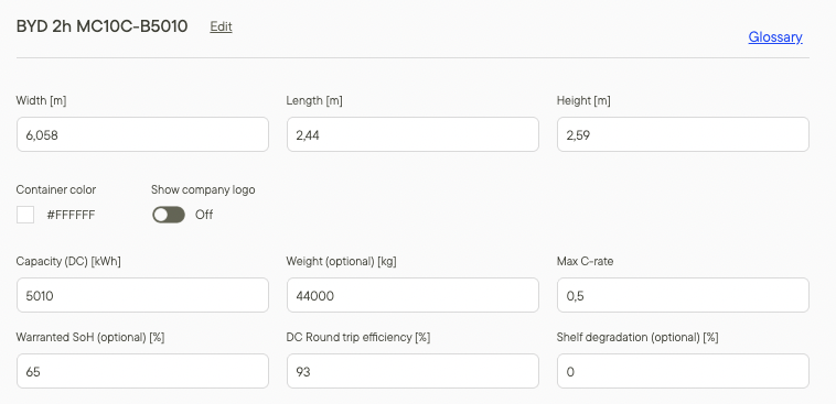
Container size: You can adjust the width, length and height of each battery to match precise specifications.
Container color: Typically dark green or white, as it helps with visuals, but this is case-by-case depending on the project. Color can also be adjusted in Glint Solar to improve visualization of the project, e.g. by coloring MV stations and battery containers differently.
Capacity: in 2025, a standard 20-ft container typically holds around 5 MWh.
Weight (optional): A typical 20-ft container with 5 MWh capacity weighs around 45 tons. This is not used in the analysis but is good for tracking foundation, lifting, and transport planning.
Max C-rate: Suppliers usually propose options ranging from 0.125 to 1.5 C-rate. This will define the maximum C-rate given the equipment. It is possible to define operations in Glint Solar that have a lower C-rate, for example to extend the lifetime of the battery.
Warranted SOH (State of Health): Typically ranges between 60% to 70%, depending on how the battery is operated. The higher the C-rate and the more cycles per day, the lower the warranted SOH.
DC round trip efficiency
Shelf degradation (optional): This value impacts on the degradation curve
MV station
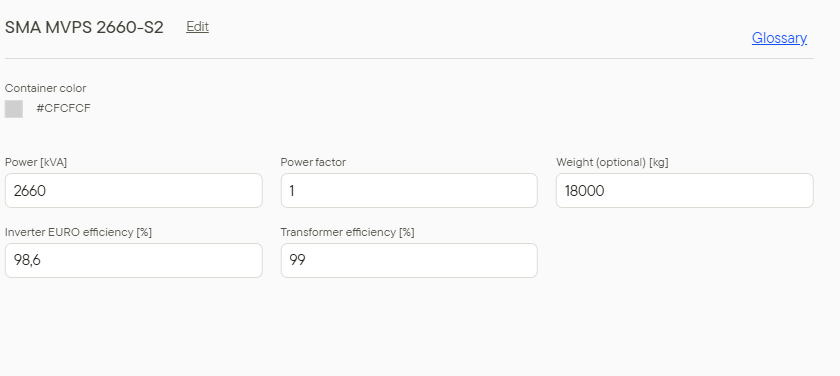
Container color: Typically dark green or white, but this can vary depending on the project.
Power (in MVA): Power can range from 1 to 5 MVA, but some manufacturers go up to 7 MVA for a 20-ft container.
Power factor: A good starting point is 1, but it is defined by the grid requirements.
Weight: The weight for a typical MV station is around 30 tons.
Inverter efficiency (Euro efficiency)
Transformer efficiency
BESS profile
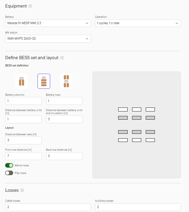
Equipment, which includes the battery, MV station, and operation profile.
BESS set definition(*), including the layout on how the containers are arranged, and specifically:
Number of battery columns: The number of battery columns depends on the hour system of the project, and the number of battery columns must be aligned accordingly.
Number of battery rows: The number of battery rows depends on the hour system of the project, and the number of battery columns must be aligned accordingly.
Distance between battery units: Normally a minimum distance of 0.5 meters is maintained.
Distance between battery units and MV station: A minimum distance of 3 meters is required between battery units and the MV station.
Distance between sets: A minimum distance of 3 meters between sets is recommended to ensure enough room for maintenance and safety.
Losses, accounting for energy losses during operation for :
- Cable losses: These losses occur due to the resistance in the electrical cables used to transfer power between components, and they depend on cable length and size.
- Auxiliary losses: These losses are associated with energy obtained from the batteries to run internal loads such as control systems, monitoring, cooling systems, and other auxiliary equipment.
This approach ensures that each component is carefully selected and integrated for optimal performance and efficiency, covering all aspects of the BESS configuration.
(*) Custom BESS sets: If need more control than what the pre-defined BESS set arrangements offer, you can use the fully custom BESS set editor. Read more about custom BESS sets here.
Additional resources
For more detail on BESS configuration, please see the articles below: