Inter-row shading
Glint ground calculates the inter-row shading. Inter-row shading occurs when a row affects the irradiation on the row behind. This loss will replace the earlier, manual “shading” loss. The inter-row shading includes two different losses:
- Irradiation losses due to inter-row shading
- Electrical losses due to inter-row shading
Irradiation losses due to inter-row shading
The first type (the irradiation loss) is the most intuitive. This is the lost irradiation due to the rows shading each other. All of the irradiation components (diffuse, beam, and ground-reflected) experience losses due to shading.
In the case case of trackers, the trackers are set up with backtracking. This backtracking is configured to eliminate any beam shading. However, tracking systems will still experience irradiation shading losses due to the diffuse and ground-reflection irradiation components.
Different packages from PVlib [1] and pvfactors [2] are used to calculate the irradiation losses due to inter-row shading.
Important parameters that affect the irradiation shading losses are; GCR, tilt and latitude.
Electrical losses due to inter-row shading
Electrical losses due to inter-row shading are caused when shade affects the overall current in the sub-module. These losses depend on the module, and the module layout. As shown in Figure 1 below, shading only one small part of a panel will block the current in the while sub-module. As shown in Figure 1, half cells are beneficial in this sense, then a smaller part of the panel is affected.
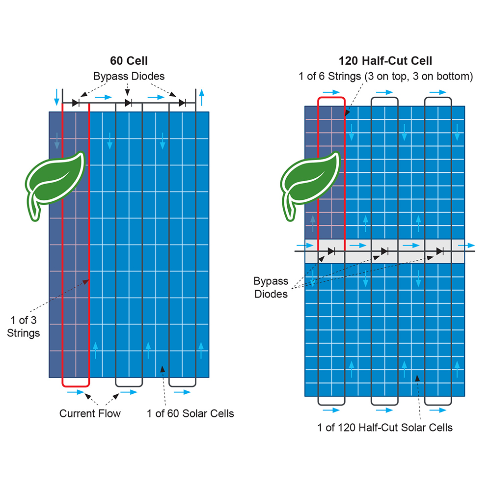
Figure 1: How shading affects the electrical current in panels. Source: https://voltaconsolar.com/blog/2020/11/28/advantages-of-half-cut-cells-photovoltaic-solar-panels/
The electrical losses are following the methodology and algorithms given by [3]. Notably, electrical losses only consider the inter-row shading from the direct (beam) irradiation. Hence, far-shading is not included in these electrical losses.
Parameters that affect the electrical shading
Shading factor: The more of the panel that is shaded (i.e by the direct irradiation), the higher electrical shading
Orientation: Portrait orientation will increase the electrical shading. This is explained by Figure 1; if the bottom of a full panel in portrait is shaded, the entire panel will experience shading effects. However, if the panel was placed in landscape, only 1/3 of the panel would experience shading effects.
Number of rows in row height: By having several multiple rows in row height, the probability of shade of the upper rows are lowered. It is therefore expected to get lower electrical shading effects with a higher number of rows in row height (assuming bypass diodes).
Assumptions:
- All panels with more than 100 cells are assumed to be half cell
- All panels are assumed to have 3 bypass diodes
- The terrain is assumed to be flat - sloped terrain does not affect shading losses
- The edge effects are neglected. In reality, the first row and the panels on the side (and between tables) are not shaded. However, Glint assumes the shading to be the same all over the row.
Validation of shading losses
In order to validate the shading losses, comparisons with PVsyst has been performed. The comparison is done in three different locations, with three different technical configurations.
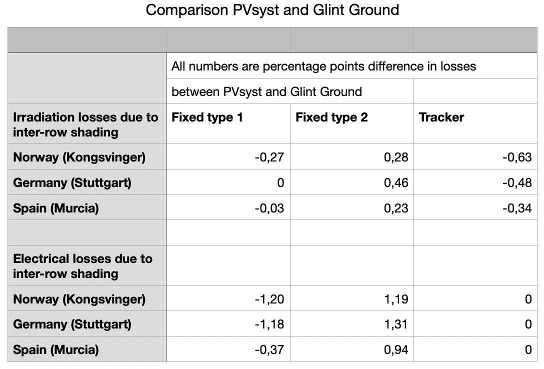
Table 1: Comparison between PVsyst and Glint Ground. The numbers are the percentage point difference between PVsyst and Glint Ground for the specific loss value
Key takeaways from comparisons:
- Irradiation losses: More or less, the Glint software delivers comparable results to PVsyst. The biggest differences are in the tracker case - the reason is because of slightly different tracking angles at the hours in the morning and evening.
- Electrical losses: As illustrated in Table 1, Glint software and PVsyst deliver different results in the electrical losses. Glint delivers lower results in the fixed type 1 configuration due to the mounting layout. The fixed type 1 configuration has two rows in the row height, and the methodology used by Glint and PVsyst handles this situation differently. The methodology used by Glint calculates a smaller loss for the upper row that experiences no shading, in comparison to PVsyst. When it comes to the Fixed type 2, the row width is equal - one panel in row width. In this case, Glint calculates a higher loss than PVsyst. This is due to differences in the mathematical model.
Decisions and simplifications:
- PVsyst shading method “Module layout” is chosen
- In order to compare with PVsyst, common irradiation data source is necessary. The Glint software was therefore ran with hourly values from PVGIS 2.0 from 2015.
Sources
[1]: https://pvlib-python.readthedocs.io/en/stable/
[2]: https://sunpower.github.io/pvfactors/
[3]: A simplified model of uniform shading in large photovoltaic arrays, Deline et al (2013): https://www.sciencedirect.com/science/article/abs/pii/S0038092X13002739