
BESS: Noise modelling
Performing noise assessments at the outset of a battery-storage project is essential. To use Glint Solar effectively, you should understand the factors it evaluates and the way it conducts its noise calculations, as acoustics can be complex. The platform analyses core parameters such as equipment sound power, terrain, and any obstacles that affect sound propagation. The sections below define the main terms, specify the user-provided inputs, and describe the calculation methodology.
Please note that noise studies generated with Glint are intended as preliminary estimates. If you plan to include them in a permit package or other formal submission, first confirm that the study’s scope, methodology, and detail satisfy the relevant regulatory requirements.
Configuring your noise modelling values
Setting up your noise modelling parameters correctly will enable you to run noise simulations with ease.
Noise Map
To display the noise map for a BESS project you need to run a BESS analysis with noise modelling activated. Once the simulation is finished, click on the three dots menu for the analysis report and select Show noise map.
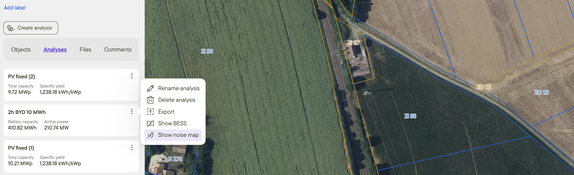 |
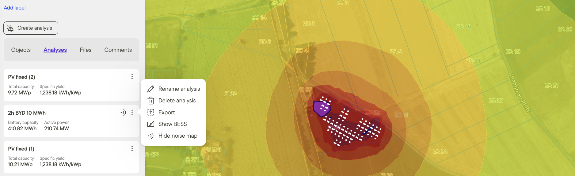 |
Custom Emitters and Receivers
It is possible to add custom noise emitters and noise receivers. Both can be added from the drawing tool.
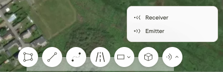
An custom emitter could be everything that emits noise. If you have the frequency (/octave) bands for your emitters (see glossary for descriptions), you can model everything you might desire. If you however only have one broadband value for your noise emitter, you can select between a couple of pre-defined alternatives.
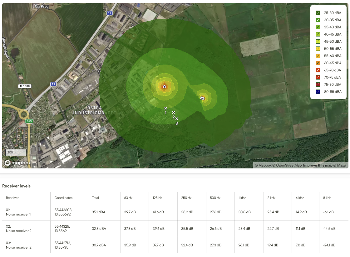
When it comes to the custom receivers, there is no configuration needed. The height of the receiver will be defined as the height of the general receivers, defined in the BESS configuration. After an noise analysis is performed, the receiver values (both broadband and for the given frequencies) will be listed in the report.
Noise Glossary
Attenuation - The progressive loss of sound energy between a source and a receiver. It results from several mechanisms—geometric spreading (sound radiates outward and intensity drops with distance), air absorption, ground and foliage absorption, and shielding by buildings or terrain.
Decibel (dB) – A measure of how loud a sound’s pressure is compared with a standard reference. The decibel scale is non-linear, logarithmic, which means that roughly every 10 dB step is heard as about “twice as loud.”
Decibel A-weighted (dBA) – A decibel value adjusted with the A-weighting filter, which de-emphasizes very low and very high frequencies to mirror average human loudness perception. Because dBA correlates better with annoyance, many environmental and occupational limits are stated in dBA.
Hertz (Hz) – A unit of frequency, equal to one cycle or vibration per second. Human hearing typically ranges from about 20 Hz to 20 000 Hz, with speech intelligibility concentrated between roughly 300 Hz and 3 500 Hz. The frequency spectrum is divided into bands.
Frequency band – A contiguous slice of the frequency spectrum bounded by lower and upper limits for example, a full-octave - as used in Glint or one-third-octave band. The common full octave frequency bands are**:** 63Hz, 125Hz, 250Hz, 500Hz, 1kHz, 2kHz, 4kHz and 8kHz. Summarized sound from all frequency bands is called broadband.
Background (residual) noise level - The underlying “baseline” sound at a location when the source of interest is not operating.
Specific noise - The portion of the total measured noise attributable solely to the source under study—such as battery-storage or MV stations.
Total (ambient) noise – The combined sound environment at a location, including background noise and the specific source. It represents the actual acoustic experience at a given moment.
Emitter – The machine, activity, or process that generates and radiates acoustic energy into the environment. Its characteristics include sound power, frequency content, and directivity pattern.
Receiver (receptor) – The point at which sound is of concern, such as a resident, a workplace or a wildlife habitat. Regulatory limits and design criteria are usually specified at the receiver location.
Ground absorbance – The proportion of sound energy that a ground surface “soaks up” rather than reflects. Soft, porous media such as grass or freshly fallen snow have high absorbance (values near 1), while hard concrete or water surfaces have low absorbance (near 0).
Tonality – The quality of a sound that contains one or more narrow-band components (tones) that stand out above the broadband background. Prominent tones can increase annoyance and may attract regulatory penalties. In Glint, however the tonal aspect of noise is not considered.
Sound power level (SWL or Lw) – The built-in acoustic output of a source. It totals all the sound energy the source sends into the air and stays the same regardless of distance or surroundings.
Sound pressure level (SPL or Lp) – The loudness that actually reaches a particular point in space. Human voice is usually measured at 70db - that is SWL, while the conversation heard from 1 meter away has a SPL of around 60 dB. Here you can find a table corelating specific SPLs with typical environmental sounds.
Noise Calculation Model and Assumptions
Calculation Model
There is no single universal formula for outdoor sound propagation. Some methods solve detailed wave-based equations, while most mapping tools rely on the simpler, standardized geometric-acoustics approach. Even then, several standards coexist. Glint uses the European CNOSSOS method, originally created for road and rail noise, whereas commercial packages such as SoundPLAN or CadnaA typically follow ISO 9613-2.
Because CNOSSOS and ISO 9613-2 handle factors like ground absorption, meteorology, and source spectra differently, their predictions will not align perfectly. Within about one kilometer of the source, the deviation in sound levels between industry noise reports and our model is usually below 3 dBA (assuming linear scale) for rural areas.
The CNOSSOS calculation model has been executed using the NoiseModelling implementation.
© Copyright 2022, UMRAE - Lab-STICC.
Assumptions
The inputs below are fixed across all projects and lean toward a conservative (higher-noise) outcome.
- Source directivity – Each emitter is treated as perfectly omnidirectional, so sound is assumed to radiate equally in every direction even though, in reality, equipment such as HVAC fans are louder on the intake/exhaust side.
- Reflections – Only first-order reflections are included. This speeds up the calculation, but may introduce inaccuracies—particularly in densely built-up areas or highly undulating terrain.
- Air temperature = 10 °C and relative humidity = 70 %. Cool, moist air carries sound farther, so these settings raise predicted levels.
- Wall absorption – All vertical surfaces are given an absorption coefficient of 0.5, representing partially reflective materials.
- Neither vegetation nor existing buildings and other structures are considered in the analysis. Battery containers and other equipment is also not included.
Inputs
Emitters
For BESS noise analysis both the battery containers and the MV stations are considered as noise emitters. You enter their sound data in the corresponding configuration tabs. Their noise comes from electrical equipment, ventilation fans, and similar hardware, and it can change with load and time of day. Glint therefore recommends modelling the worst-case operating condition.
The acoustic information you receive from suppliers may be limited. Battery data sheets often provide just one A-weighted sound-pressure level—for example, 80 dB(A) measured 2 m from the container. For a more accurate study, ask the manufacturer for a detailed acoustic report. Ideally, supply sound-power-level (SWL) values split into frequency bands; these yield the highest precision in the Glint model.
Below are instructions on how to set up your emitter correctly.
Simple (broadband noise) or Advanced (Frequency Bands)?
Select simple when you have only one overall sound-level for the source. Select advanced when you possess the sound power broken down into full octave bands; this option is preferred whenever this data are available.
Manufacturers sometimes supply one-third-octave levels—for example 63, 80, 100, and 125 Hz. These four values belong to a single full octave band (63–125 Hz). Combine the three one-third-octave values that sit inside each octave band before entering them in Glint. Because decibels are logarithmic, use a dedicated online calculator.
If you supply only a single broadband level, Glint automatically splits it into octave-band values using a reference industry-average spectrum. This built-in spectrum is intentionally conservative.
Power Level (SWL) vs Pressure Level (SPL)
This hinges on the type of data you have: a sound-pressure level measured at a set distance, or the source’s intrinsic sound-power output. If your noise level is SPL then the SWL is recovered using the following formula: SWL = SPL + 10 log₁₀ (4 π r² / Q)
where r is the measurement distance in meters and Q is the directivity factor. Using Q = 1.35 provides a conservative estimate.
dB or dbA?
It depends on whether your figure is an unweighted decibel value—typically written as Lp for SPL or Lw for SWL—or whether it has already been adjusted for human hearing, in which case it can be labelled LpA or LwA.
Source Height
For a battery storage container this usually ranges from 1.5 to 2 meters, much depending on the location of the HVAC unit.
Acoustic Parameters
Apart from the emitters specification you also need specify parameters of the sound analysis in the profile. They are explained below,
Include Noise analysis
Turn this switch on if you want Glint to perform the noise calculation; leave it off to skip the step. A full run typically takes two to five minutes, depending on project size and complexity.
Ground Absorbance (G value)
Enter a single value between 0 and 1 describing how much sound the ground around the site absorbs. Because real terrain mixes many surfaces, choose a representative figure.
| Description | G value |
|---|---|
| Very soft (snow or moss-like soft forest floor) | 1 |
| Compacted field and gravel (compacted lawns, park area) | 0.7 |
| Compacted dense ground (gravel road, car park) | 0.3 |
| Hard surfaces (most normal asphalt, concrete, water) | 0 |
Receivers’ Height
Specify the elevation above ground at which sound-pressure levels are reported. For reliable results use at least 2 m to minimize ground effect errors.
Include Terrain
Terrain's elevation is an important factor when modeling noise propagation, as it can both reflect and diffract sound. Including terrain will yield more accurate results, although it may increase simulation time.
Noise Wall
Noise walls are the primary strategy for mitigating sound from BESS installations. Acoustic barriers can be modelled as 3D objects with typical heights between 3–5 meters. They are assumed to have no sound transmission, consistent with high-density materials such as concrete or composite structures, with an STC (Sound Transmission Class) rating above 60. All incident noise is therefore either reflected or absorbed, with an absorption coefficient of 0.5, a conservative estimate representing textured concrete or perforated/slotted metal panel surfaces.
Background noise
You can specify a uniform background noise level to be included in your analysis. This value is added to the specific noise generated by on-site equipment, resulting in a noise map that shows the total emission.
Additional resources
For more detail on BESS configuration, please see the articles below: