
Equipment and layout
PV module
A PV module, or photovoltaic module, is a key component of a solar energy system, consisting of interconnected solar cells housed within a protective enclosure. It converts sunlight into electricity through the photovoltaic effect, serving as the building block for solar panels used in various applications, including solar parks, residential rooftops, and commercial installations.
Main module types
Photovoltaic (PV) modules come in a variety of types. The type refers to the technology used in the solar cells of a PV module, such as monocrystalline, polycrystalline, or thin-film. The type of technology influences the module's efficiency and cost.
Bifacial
Most new solar panels used today in ground utility pv are bifacial panels. A bifacial panel can convert the irradiation on the back side of the panels to electricity. A monofacial panel can only make use of the irradiation on the front side of the panels.
PAN file
A PAN file typically refers to a performance analysis file containing data on the electrical performance of individual solar panels. It includes information such as voltage, current, and power output, which is crucial for evaluating the efficiency and reliability of PV panels in solar installations. Suppliers provide these files and ideally they should be certified by a known testing organization.
String
In the context of PV power plants, strings are electrical circuits formed by connecting multiple solar panels in series. Strings are then connected in parallel to form the overall electrical configuration of the solar array. The design of strings affects the voltage and current characteristics of the system, impacting the choice of inverters and the overall performance of the PV power plant. Proper string design considers factors such as shading, module characteristics, and electrical compatibility to optimize energy production and system reliability.
Mounting system
There are several different types of mounting systems that can be used for PV power plants, such as fixed-tilt support structures, single- or double-axis tracking structures, marine-grade support structures that prevent corrosion, and more. Glint Solar supports fixed tilt, single-axis tracker and east-west mounting types.
PV table
PV table refers to a group of modules installed in a single independent mounting structure (fixed or tracker system).
Table length: The number of modules next to each other in one row. In the example below: 28 modules.

Table width: The number of modules next to each other in vertical direction. In the example above: 2 modules.
Module elevation: The height at which the solar panels are mounted above the ground surface. Adjusting module elevation affects the bifacial effect in case of using facial modules.
Table spacing: Table spacing in PV tables for solar parks denotes the distance between adjacent rows or columns of solar panels.
In the figure below, note the space in between the two tables. The space has to be wide enough to allow dilatation of the metallic structure in case of different temperatures.

Tracker
Rotation angle: The degree to which the tracking system adjusts the orientation of solar panels to follow the sun's path throughout the day, maximizing sunlight exposure. By dynamically changing the angle of the panels, trackers optimize energy capture and enhance overall efficiency of the solar park system
Axis elevation: The height at which the rotational axis of the tracking system is positioned above the ground, determining the range of motion for panel orientation adjustments.
Tracker spacing: The distance between individual tracker units within the solar park layout.
Module position
Landscape: Landscape orientation refers to positioning solar panels horizontally, with the longer side of the panel parallel to the ground, optimizing sunlight exposure throughout the day.
Portrait: Portrait orientation in solar parks involves positioning solar panels vertically, with the longer side of the panel perpendicular to the ground, maximizing sunlight exposure during the morning and afternoon hours. The general trend in ground mounted parks is to use portrait orientation.
Row distance
Row distance can either be defined as "panel to panel distance" or as "axis to axis distance". Axis to axis is the default in Glint Solar. See Figure 1 below for an illustration of the difference between the two definitions. Axis to axis distance can also be referred to as "pitch". For a single axis tracker system, a tilt of 0 is assumed when calculating the distance from panel to panel. For single axis trackers, backtracking is enabled.
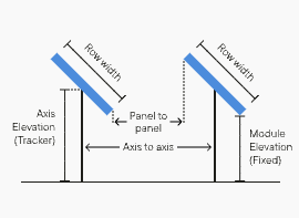
Pitch (axis to axis): The distance between the axes of adjacent rows of solar panels, determining the row-to-row spacing. Optimizing pitch ensures adequate sunlight exposure for all panels while minimizing shading between rows, thereby maximizing energy production efficiency.
Inter-row space (panel to panel): The distance between a solar panel from one row to the next. Proper inter-row space allows for airflow, reduces shading between panels, and facilitates maintenance access, ensuring optimal performance and longevity of the solar park system.
Orientation
In the northern hemisphere, the optimal directional orientation for all panels is true south. However, in some markets where producing energy during peak demand times is encouraged, it may be more financially beneficial to orient the panels facing southwest to generate the most power in the afternoon.
Tilt: Each location will have its own ideal tilt angle that maximizes annual sun exposure based on the latitude of the site. For fixed-tilt panels, the optimal angle may need to be adjusted due to factors like panel soiling, shading, and seasonal irradiation distribution. The higher the panels are tilted, the more they will be cleaned by rain but also the more they will shade panels in rows behind them
Azimuth: Where the panel surface faces, measured in degrees from true north. This means a panel that faces true south has an azimuth of 180 degrees.
Alignment
Centre: Center alignment positioning solar panels relative to a central reference point or axis, ensuring uniformity and symmetry in the layout.
Grid: Grid alignment refers to positioning solar panels in a coordinated pattern, often parallel or perpendicular to each other, to create a visually organized layout.
Ground Coverage Ratio (GCR)
Ground Coverage Ratio in solar parks refers to the ratio of the total ground area covered by solar panels to the total area of the solar park site. It quantifies the extent of land utilization for solar energy generation, guiding decisions on optimal panel placement and overall park layout to maximize energy production efficiency.
The Ground Coverage Ratio (GCR) in solar parks is calculated by dividing the total area covered by solar panels by the total area of the solar park site.

For example, if a solar park has a total area of 10,000 square meters and the solar panels cover 6,000 square meters, the GCR would be:

In this case, the Ground Coverage Ratio would be 0.6 or 60%, indicating that 60% of the solar park site is covered by solar panels.
Inverter
Inverters are an essential component of solar parks that convert the direct current (DC) electricity generated by solar panels into alternating current (AC) electricity suitable for use in the electrical grid or for local consumption. They play a crucial role in maximizing the efficiency and usability of the solar energy generated within the park.
String inverter: A string inverter is a type of inverter that converts the DC power generated by multiple solar panels connected in series (or "string") into AC power for grid connection. It is convenient for sites that are made of various areas with different topography features. String inverters optimize the performance of the site better than central inverters.
Central inverter: A central inverter in solar parks is a larger-scale inverter that converts the DC power generated by multiple strings or arrays of solar panels into AC power for grid connection. It is often installed at a central location within the solar park.
OND file: An OND file, or "Operating and Notification Data" file, is a digital file containing information related to the operational status and performance data of inverters in a solar park. It includes data such as power output, efficiency, and any error or warning notifications, providing valuable insights for monitoring, maintenance, and troubleshooting purposes. Suppliers provide this file and ideally they should be certified by a known testing organization.
Transformers
Transformers are devices used to increase or decrease the voltage of electricity generated by inverters in the solar plant before it is transmitted to the grid or local distribution network. They play a crucial role in managing voltage levels, ensuring efficient power transmission, and facilitating integration with the existing electrical infrastructure.
Transmission transformer
A transmission transformer is a large-scale device used to step up the voltage of electricity generated by inverters in the solar plant for efficient long-distance transmission to the grid or substation. It enables the electricity to be transmitted at higher voltages, reducing losses during transmission over long distances.
Distribution transformer
A distribution transformer is a smaller-scale device used to step down the voltage of electricity from the grid or transmission lines to a lower voltage suitable for distribution to end users or local consumption within the solar park. It ensures that the electricity is delivered safely and efficiently to homes, businesses, or other facilities connected to the distribution network.
Additional resources
For more information on configuring your PV settings in Glint Solar, see Adjusting the PV settings.
For instructions on adding PAN files for modules and OND files for inverters see this article.
Learn more about the technical concepts described above in the Solar Site Planning Guide: