Losses in Glint Solar
Losses in a photovoltaic (PV) power plant refer to the reduction in energy output compared to the theoretical maximum output under ideal conditions. Various factors contribute to losses in a PV system, and understanding these losses is crucial for accurately estimating the actual energy production and optimizing the performance of the power plant. Glint Solar includes losses in a user-friendly format to ensure yield estimates are accurate and fast.
Losses in Glint Solar
A valuable part of Glint Solar is the PV calculation which divides losses into two groups:
- Losses provided by the user in the PV profile settings.
- Losses provided by the Glint calculation.
The calculated losses are presented in the “Losses” diagram in the report. These delta values are values compared to STC (standard test conditions). Some values therefore might be positive, i.e an energy gain. There are also other small losses in the process which are not included in this illustration.
Manual input losses
Soiling: Soiling losses refer to the reduction in energy output caused by the accumulation of dirt, dust, or other particulate matter on solar panels, hindering the absorption of sunlight and diminishing overall efficiency. Regular cleaning and maintenance are essential to mitigate these losses and ensure optimal performance of solar power systems.
Availability: Availability losses denote the downtime or reduced performance of solar panels due to factors such as system maintenance, grid outages, or equipment failures, leading to intermittent or decreased energy generation. Effective monitoring and prompt troubleshooting strategies are crucial for minimizing these losses and maximizing system uptime.
Wiring: Wiring losses refer to energy dissipation caused by resistive losses in the electrical wiring connecting solar panels to the inverter or other components, leading to decreased system efficiency and potential power degradation.
Light-induced degradation loss: Light-induced degradation losses occur due to the initial decrease in efficiency when solar panels are exposed to sunlight, primarily affecting certain types of silicon-based photovoltaic cells, notably monocrystalline PERC cells, leading to a temporary reduction in power output until the cells stabilize over time.
Shading: Shading losses in the "other losses" section only include near shading. Far shading is taken into account in the calculation phase. Near shading losses include shading from nearby objects, for instance trees or inter-row shading. This shading will both affect the actual direct irradiance that hits the module, but also electrical mismatch losses that occur.
Annual degradation: Annual degradation losses refer to the gradual reduction in solar panel efficiency over time due to factors like material degradation, environmental exposure, and usage, typically ranging from 0.5% to 1% per year, impacting long-term energy output and warranting periodic performance evaluations for maintenance and optimization.
Snow: Snow losses occur when snow accumulates on solar panels, blocking sunlight and reducing energy production, necessitating removal or tilt adjustments for optimal performance during winter months.
Connection: Connection losses pertain to energy dissipation at the points where solar panels are interconnected, such as junction boxes or combiner boxes, due to resistive losses, poor connections, or mismatched components, leading to decreased system efficiency and requiring proper installation and maintenance to minimize power degradation.
Nameplate rating: Nameplate rating losses occur when actual system performance falls short of the rated capacity specified by the manufacturer.
Mismatch: Mismatch loss refers to the decrease in overall energy output caused by variations in the electrical characteristics of individual solar panels within a PV array. Not all the modules are exactly the same.
Total loss: The sum total of all the above losses.
Calculated losses
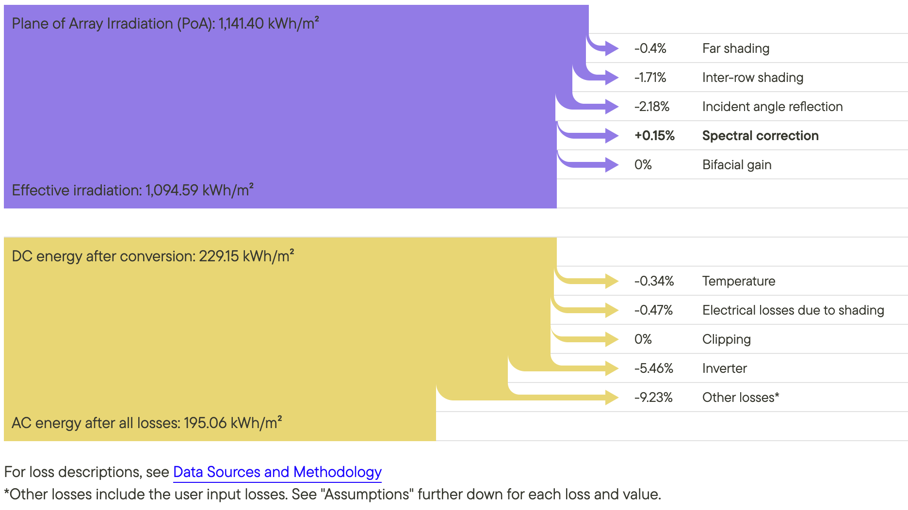
Far shading: Glint has implemented a far shading algorithm, which calculates the shading losses from the surrounding, distant terrain. For instance, this is useful when there are mountains around a site, or the site is located in a valley. Note: This is not “near shading”; if the shading terrain is in close proximity of the site, this shading is not included.
Inter-row shading: The lost irradiation due to inter-row shading. See Engineering concepts for more information on inter-row shading.
Incident angle reflection: Unless the PV array is mounted on a two-axis tracker, the incident angle for the direct component of the solar radiation will not be normal except for a few rare instances, depending on the orientation. When the angle of incidence is greater than zero, there are optical losses due to increased reflections from the module materials that need to be quantified.
There are two IAM components: Direct IAM losses and diffuse. In Glint’s calculations, it is assumed that the panel has an anti-reflecting (AR) coating.
Spectral mismatch: A spectral mismatch correction factor is utilized to correct the spectral mismatch between the PV reference solar cell and the actual conditions. STC in laboratories have a different spectral response than the sun. There is therefore a spectral mismatch between the actual ground conditions and in laboratories. NOTE: The spectral mismatch correction can also be positive. In this case, it is actually a energy gain (compared to STC values).
Bifacial gain: The added irradiation of the rear side, after taking into account the bifaciality factor. Read more about the bifacial calculation here: PV Analysis — Methodology and data sources.
Temperature: Under STC, the reference cell temperature is 25 degrees Celsius. Cell temperature affects the performance, and is dependent on factors such as ambient temperature, isolation technology and wind. NOTE: Some conditions can yield a positive energy gain, compared to STC. If the cell temperature is below 25 degrees (which is the reference temperature in STC), the performance will increase.
Electrical losses due to shading: The electrical losses due to inter-row shading. See Losses and Equipment and layout for more information on electrical losses due to shading.
Clipping: Clipping losses are a direct consequence of the DC-AC ratio. See explanation on the clipping and clipping losses earlier in this article. A higher DC-AC ratio will imply a higher clipping loss.
Inverter: The inverter efficiency is never 100%. The inverter losses are energy lost in the inverter.
Other losses: The other losses are those entered manually in the profile settings.
Additional resources
Wondering how losses recorded in Glint compare to those in PVsyst? Compare them here.
Want to adjust your PV profiles? Learn how to do so here.